ChargePilot® hardware packages & scope of delivery
Component mounting: The ChargePilot® hardware requires approximately 14 subdivision units of space when installed in the sub-distribution. The required height and depth are: (H)30 cm and (D)21 cm. To avoid heat generation, there should be a distance of one between the components. The ChargePilot® hardware components are not protected against water and dust. Depending on the mounting location, we recommend mounting in a control cabinet with protection class IP54 or higher.
ChargePilot®: Static Hardware
Scope of delivery for static load management
Name | Picture | Description | Quantity |
|---|---|---|---|
ChargePilot® Controller: |  | The ChargePilot® Controller is the centerpiece of ChargePilot®. With its two network ports, it connects to the internet on the one hand and establishes a local network to the charging stations on the other. Within the controller, all optimization processes for charging and energy management run locally and are transmitted to the charging stations. The controller is connected to the network switch with the enclosed network cable and mounted on the DIN rail (TS 35 / EN 50022) in the control cabinet. | 1 |
8-Port RJ-45 + 2-Port SFP Network-Switch: Teltonika | 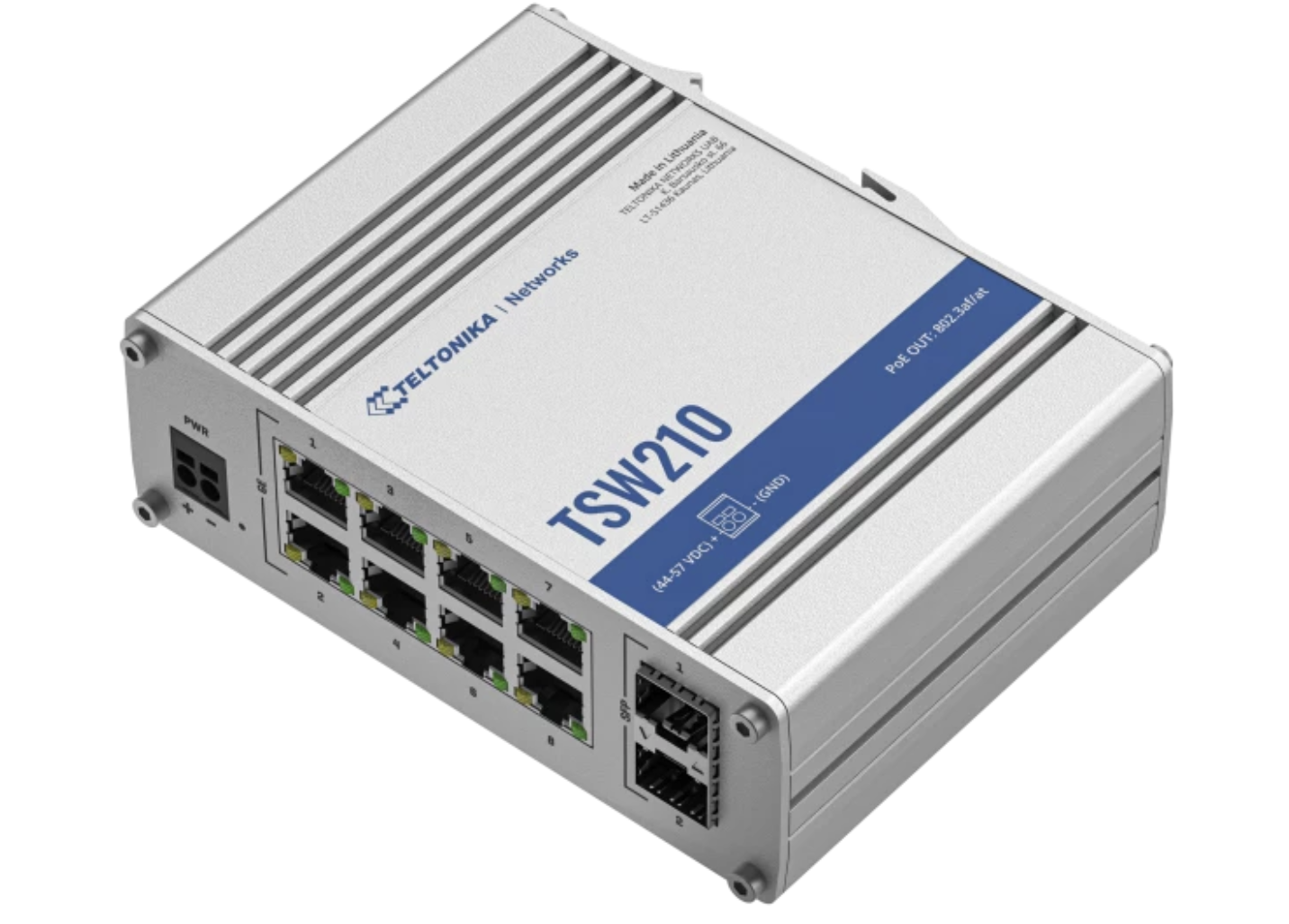 | The network switch ensures communication between the ChargePilot® Controller and the individual charging stations. In addition to the 8 RJ 45 ports, the selected model also provides 2 SFP ports to lay the foundation for fibre optic connections. The switch is connected to the controller via network cable and mounted on the DIN rail (TS 35 / EN 50022) in the control cabinet. The charging stations are connected to the network switch using network cables. If a larger or additional network switch is used, it may not be possible to mount it on the DIN rail in the control cabinet and it will require a separate network cabinet. | 1 |
Switching power supply unit 230 V AC →24 V DC: Mean Well MDR-60-24 | 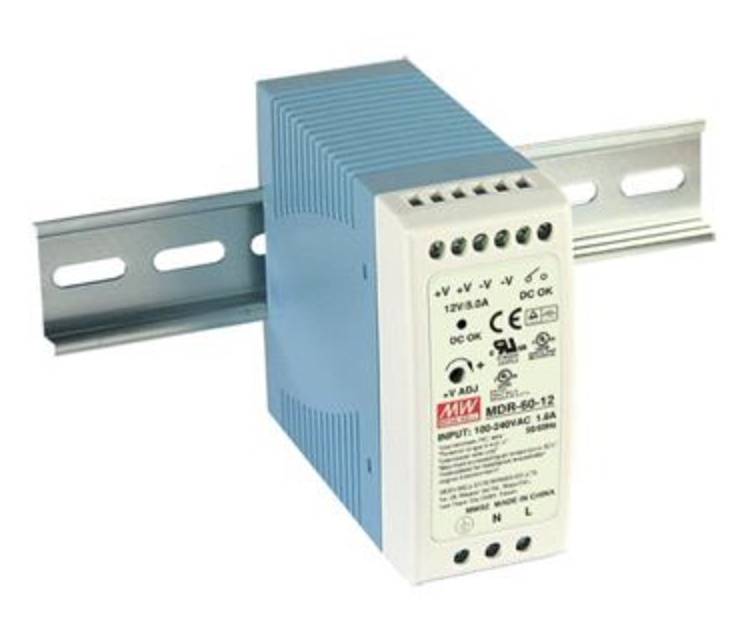 | The switching power supply unit serves as the central 24 V DC power supply for the ChargePilot components and can also supply the Connectivity Router (if necessary) in addition to the switch and controller. It is connected to the controller and the network switch and mounted on the DIN rail (TS 35 / EN 50022) in the control cabinet. On the AC side, the switching power supply unit is connected to 230 V. | 1 |
Network-Patch-Cable: 2 x RJ45 plugs, 25cm | 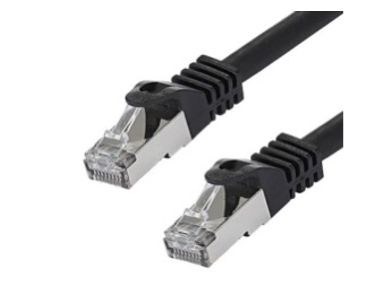 | The network patch cable connects the controller to the network switch. | 1 |
Circuit breaker 1-pole B16: Hager MBN116 | 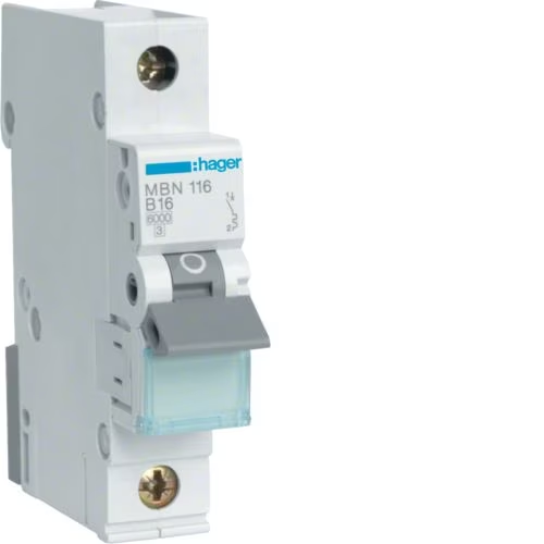 | The miniature circuit breaker 1-pole B-characteristic (Hager MBN116) separately protects the ChargePilot power supply. | 1 |
 | 1 | ||
 | 1 |
ChargePilot®: Dynamic Hardware
Scope of delivery for dynamic load management
Name | Picture | Description | Quantity |
|---|---|---|---|
ChargePilot® Controller: | | The ChargePilot® Controller is connected to the network switch using the enclosed network cable and mounted on the DIN rail (TS 35 / EN 50022) in the control cabinet. | 1 |
8-Port RJ-45 + 2-Port SFP Network-Switch: Teltonika | | The network switch is connected to the controller by means of a network cable and mounted on the DIN rail (TS 35 / EN 50022) in the control cabinet. The charging stations are connected to the network switch using network cables. If a larger or additional network switch is used, it may not be possible to mount it on the DIN rail in the control cabinet and it will require a separate network cabinet. | 1 |
Switching power supply unit 230 V AC →24 V DC: Mean Well MDR-60-24 | | The switching power supply unit is connected to the controller and the network switch and mounted on the DIN rail (TS 35 / EN 50022) in the control cabinet. On the AC side, the switching power supply unit is connected to 230 V. | 1 |
Network-Patch-Cable: 2 x RJ45 plugs, 25cm | | The network patch cable connects the controller to the network switch. | 1 |
Measuring transformer meter: ABB B24 112-100 | 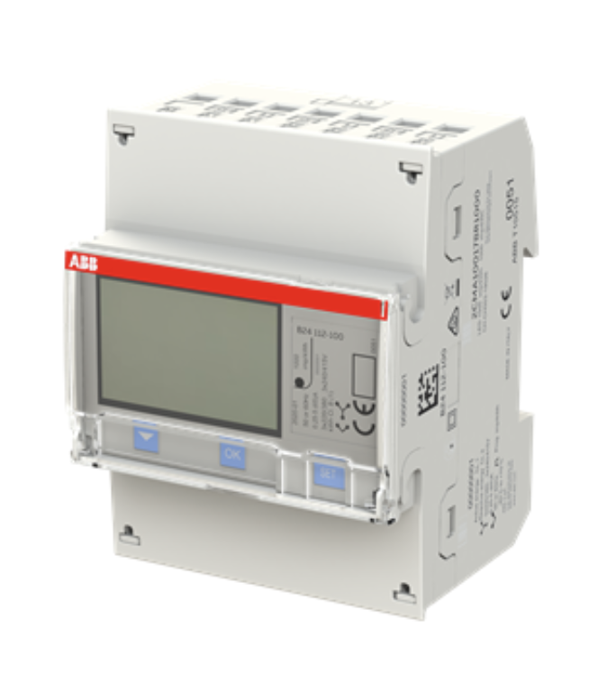 | The transformer meter transmits the current and voltage data on the three mains phases transmitted by current transformers (not supplied) to ChargePilot via an RS 485 connection. It is connected to the ChargePilot controller via an RS 485 cable. | 1 |
Circuit breaker 3-pole B16: Hager MBN316 |  | The miniature circuit breaker 3-pole B-characteristic (Hager MBN316) serves as a pre-fuse for the measuring transformer meter. | 1 |
RS 485 Cable: 3m | The RS 485 cable is connected to the ChargePilot controller with one of the supplied terminating resistors and is used for communication between the ChargePilot transformer meter and the controller via Modbus. | 1 | |
| 1 | ||
| 1 |
ChargePilot® Box: Static Hardware
Scope of delivery for static load management with ChargePilot® Box
Name | Picture | Description | Quantity |
|---|---|---|---|
ChargePilot® Controller: | | The ChargePilot® Controller is connected to the network switch using the enclosed network cable and mounted on the DIN rail (TS 35 / EN 50022) in the control cabinet. | 1 |
8-Port RJ-45 + 2-Port SFP Network-Switch: Teltonika | | The network switch is connected to the controller by means of a network cable and mounted on the DIN rail (TS 35 / EN 50022) in the control cabinet. The charging stations are connected to the network switch using network cables. If a larger or additional network switch is used, it may not be possible to mount it on the DIN rail in the control cabinet and it will require a separate network cabinet. | 1 |
Switching power supply unit 230 V AC →24 V DC: Mean Well MDR-60-24 | | The switching power supply unit is connected to the controller and the network switch and mounted on the DIN rail (TS 35 / EN 50022) in the control cabinet. On the AC side, the switching power supply unit is connected to 230 V. | 1 |
Network-Patch-Cable: 2 x RJ45 plugs, 25cm | | The network patch cable connects the controller to the network switch. | 1 |
Circuit breaker 1-pole B16: Hager MBN116 | | The miniature circuit breaker 1-pole B-characteristic (Hager MBN116) separately protects the ChargePilot power supply. | 1 |
ChargePilot® Box | 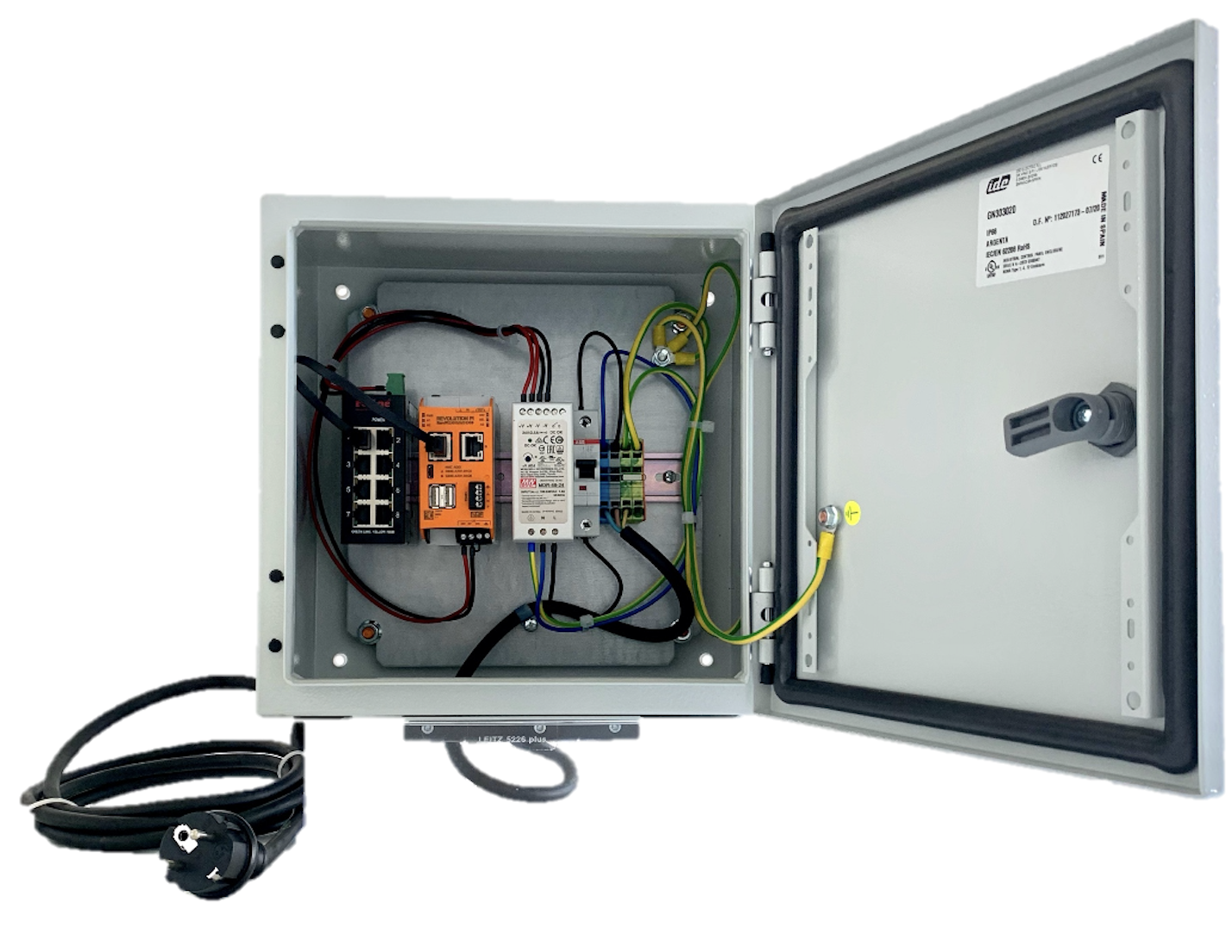 | All components pre-assembled in an outdoor-suitable housing (the ChargePilot Box) made of coated sheet steel with individually equipable cable feed-throughs and Schuko plug (3m) Temperature range: -20 °C to +35 °C Protection class: IP66, NEMA 1, 12, 4, IK08 | 1 |
| 1 | ||
| 1 |
ChargePilot® Box: Dynamic Hardware
Scope of delivery for dynamic load management with ChargePilot® Box
Name | Picture | Description | Quantity |
|---|---|---|---|
ChargePilot® Controller: | | The ChargePilot® Controller is connected to the network switch using the enclosed network cable and mounted on the DIN rail (TS 35 / EN 50022) in the control cabinet. | 1 |
8-Port RJ-45 + 2-Port SFP Network-Switch: Teltonika | | The network switch is connected to the controller by means of a network cable and mounted on the DIN rail (TS 35 / EN 50022) in the control cabinet. The charging stations are connected to the network switch using network cables. If a larger or additional network switch is used, it may not be possible to mount it on the DIN rail in the control cabinet and it will require a separate network cabinet. | 1 |
Switching power supply unit 230 V AC →24 V DC: Mean Well MDR-60-24 | | The switching power supply unit is connected to the controller and the network switch and mounted on the DIN rail (TS 35 / EN 50022) in the control cabinet. On the AC side, the switching power supply unit is connected to 230 V. | 1 |
Network-Patch-Cable: 2 x RJ45 Stecker, 25cm | | The network patch cable connects the controller to the network switch. | 1 |
ChargePilot® Box | | All components pre-assembled in an outdoor-suitable housing (the ChargePilot Box) made of coated sheet steel with individually equipable cable feed-throughs and Schuko plug (3m) Temperature range: -20 °C to +35 °C Protection class: IP66, NEMA 1, 12, 4, IK08 | 1 |
Measuring transformer meter: ABB B24 112-100 | | The transformer meter (incl. 2x 120Ω terminating resistor) is connected to the ChargePilot Controller via RS 485 cable. | 1 |
Circuit breaker 3-pole B16: Hager MBN316 | | Circuit breaker 3-pole B-characteristic (Hager MBN316) The power meter is installed according to the manufacturer's instructions and protected by the 3-pole miniature circuit breaker supplied. | 1 |
RS 485 Cable: 5m | The RS 485 cable is connected to the ChargePilot controller with one of the supplied terminating resistors and is used for communication between the ChargePilot transformer meter and the controller via Modbus. | 1 | |
| 1 | ||
| 1 |