Advanced settings for admins
In the Advanced Settings area, ChargePilot® Admins can independently store location parameters. Below you will find an explanation of how to set the correct parameters for your location in the ChargePilot® web portal.
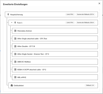
Main fuse
The main fuse specifies the limit for the mains supply of the entire charging fleet incl. auxiliary loads with dynamic load management. This may not exceed the protection level of the main fuse. In the case of static load management, this limit is to be understood as the possible total power of the entire charging infrastructure connected to ChargePilot® and does not necessarily have to correspond to a physical protection level. In the case of dynamic load management, this limit applies to all consumers and generators connected to it, i.e. including adjacent building loads, possible PV generation and the charging infrastructure. The charging infrastructure is always supplied with the remaining available electricity on a lower priority basis.
Here you have the option to change the stored value for this limit. Here, the structural and contractual specifications (purchased connected load) for this main fuse limit must be observed, e.g. existing fuses that may not be exceeded.
Please also ensure that the sum of the set fallback values is below the set main fuse limit (for more information on fallback values, see Charging Stations and Building Load). Please note that the values are given in amperes. A limit that is set too high can, among other things, cause the fuse to intervene and thus interrupt your power supply, as well as cause damage to your infrastructure.
Sub-fuses
All sub-fuses indicate the maximum limit with which the respective subordinate charging stations can be supplied. In practice, this usually corresponds to the fuse level of distribution cabinets that feed the charging infrastructure. It is important that these distribution cabinets only supply charging stations that are controlled with ChargePilot®.
Here you have the option to adjust the name of the sub-fuse as well as to change the limit value of the sub-fuse. Please note that the values are given in amperes. There is no possibility to delete or add limit values completely.
Charging stations
In the Charging Stations section, you can change certain parameters of the individual charging stations. These include the names of the charging points as well as other parameters of the charging stations. One parameter is the maximum current per charging point that can be entered. If no fallback value is entered for the charging station or if the corresponding charging station does not support this function, the maximum current is deducted from the available charging power in the event of a loss of connection to the charging station. (see Fallback)
Fallback
The fallback value determines the maximum available power at the charging station in case the charging station loses its connection to the ChargePilot® Controller. This fallback value is given in amps and is subtracted from the available charging power at the fuse to which the charging station is connected and at the fuses before it.
For charging stations with two connections, the fallback value is divided between these connections. For these charging stations, the fallback value must be set to at least 12 A, since most charging stations (e.g. ICU Double) only charge with at least 6 A.
The fallback value can be set for all charging stations that support this function. If the charging station does not support fallback values and the charging station loses the connection to the ChargePilot® Controller, the capacity of the charging station is subtracted from the available charging power at the fuse to which the charging station is connected and at the fuses in front of it.
Grid connection
In this section you can select whether the charging point has a single-phase or three-phase mains connection. The selected mains connection influences the fallback value, which is subtracted from the available charging power if the charging station loses the connection to the ChargePilot® Controller. If the charging point has a single-phase connection, the fallback value is only active for this connected phase.
Phase rotation and ability
The phase allocation is relevant in order to map the actual phase rotation of the charging stations and thus distribute the available power to the vehicles to be charged with phase accuracy. You also have the option in this area to change the capability per charging point. The set capability is then active for all connected phases.
Building load
If dynamic load management is used, you have the option of setting a fallback value for the building load and a safety buffer. The fallback value takes effect when the connection to the installed meter is interrupted. The safety buffer provides additional safety by adding it to the measured value of the building load before the available electricity is distributed to the charging infrastructure.